Introduction
Many times when a casual observer is watching my gliders circle around I am asked the question, “What is making the glider turn and why is the glider circling? I try to explain to them that I do not have any active controls on the glider (it is not a Radio Controlled glider) and that the glider is adjusted or trimmed before it is launched so it will circle. Most will quickly response with, "Why not make the glider go straight?"
Why We Circle
Yes, it is very true that a glider will have a better sink rate or stay up longer for a given height if the glider goes straight. Making the glider circle adds complications, so why turn? Well if one is flying inside a building, the answer is clear; a good glider which flies in a straight line will hit a wall before it actually touches down on the floor. So for indoor gliders the building is typically not long enough to obtain a good duration time. What about outdoor gliders? If you outside there are no walls, so gliders which are intended to fly outside go straight? Well, there are reasons why outdoor gliders are trimmed to circle too and the main reason is thermals. Thermals are small pockets of raising air, and if one circles and get into one of these pockets, there is a good chance the glider will stay in the thermal. Nothing is more beautiful than watching your glider get caught in a thermal and go out of sight.
Basic Forces and Controls of a Glider
First if we think about the glider as being just a ball and somehow we magically can exert a force on this ball what forces do we need to exert on this ball to make it turn? Newton's First Law states that an object will remain at rest or in uniform motion in a straight line unless acted upon by an external force. So if we want to turn we need a force pushing the glider to turn or in physics terms we need some centripetal acceleration.
Centripetal Force is define as F=m*v/r^2. Where F is the force required to make the glider turn, m is the mass, v is the velocity of the glider and r is the radius of the turn. Now for a constant turn or acceleration we need a constant force.
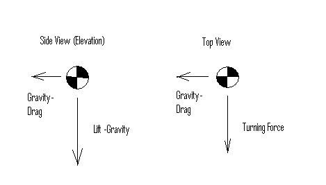
If this ball is now imagined to be the center of gravity of the glider for a glider in stable, equilibrium flight having a constant radius left turn then the forces at the CG are shown in the free body diagram below.

Note there is typically a constant downward force (Lift Force minus Gravitational Force) which gives a constant sink rate. There is also a constant force in the horizontal direction which gives a constant velocity.
Now a glider has three dimensions or axis’s about the CG, Pitch (up and down), roll(left or right about the axis of the fuse)and yaw (left or right to the direction of forward travel). Typically an airplane has control surfaces to controls these axis’s. The elevator controls pitch, the ailerons for roll and the rudder for yaw. Now a real complication which Freeflighters can use to their advantage is that these three control surfaces effect or mix two of more of these axis’s. For example if an RC plane is trimmed, flying straight and level and left rudder is applied, the typically RC plane will not only yaw left but also roll left and pitch down. As a Freeflighter, if we add some rudder to a model we probably need to add some roll and some up to make the model fly correctly.
What Makes A Glider Have The Minimum Sink Rate
Now if we assume we are going to circle then the next question is how do we go about this and lose the least amount of duration time. The duration time is basically the sink rate of a glider. To minimize the sink rate 1 it is known that Cl^1.5/Cd needs to be as large as possible. Where Cl is the lift coefficient of the glider and Cd is the drag coefficient. Cl and Cd basically don’t change if the model wing is banked but forces about the CG do because A (the area) changes for the lift force while the drag force area remains constant. Therefore to understand this issue we must study the forces on the detailed parts of the glider.
Detailed Forces
A glider in flight basically converts the potential energy (or height) into kinetic energy (or speed). The purpose of creating speed is to create a lift force defined by the equation:
The Lift force;
Fl=Cl*.5*A*p*v^2 where A is the lifting area of the glider, p is the density of air and v is the velocity of the glider.
An after effect of creating speed and lift is drag. Drag is undesirable and comes in a few forms. There is sectional drag, which is the drag created by an object shape and cross-section. It is defined by the equation;
Fd=.5*Cda*A*p*v^2 where A is the cross area, p is the density of air and v is the velocity of the glider.
Then there is skin drag which is defined by the equation;
Fd=.5*Cdf*A*p*v^2 where A is the surface area, p is the density of air and v is the velocity of the glider.
And finally there is induced drag, drag created because lift was created. Induced drag is defined by the equation; Fd=.5*Cdi*A*p*v^2 where A is the area of the lifting surface, p is the density of air and v is the velocity of the glider.
If one adjusts the Cda, Cdf and Cdi coefficients so they are normalized to one area then Cdt=Cda+Cdf+Cdi where Cdt is the total drag coefficient. The basic drag equation then becomes:
Fd=.5*Cdt*A*p*v^2 where A is the normalized area, p is the density of air and v is the velocity of the glider.
Detailed Components
Every surface; wing, elevator and rudder creates lift and drag per the above equations. Now to create the turning force we need to examine the glider and basic glider parts in more detail. For a glide the parts which really can create forces are the wing, elevator and rudder. We will assume the fuse doesn’t create any forces just hold all the parts in line and together. I believe since the area of the fuse is small compared to the wing, elevator and rudder this is a good assumption.
The Pitch Axis
Let’s first look at the simplest example about the pitch axis. We will assume no dihedral in the wing or stab and that everything in on the same line.
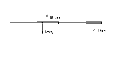
Then the following free body diagram can be drawn:

The glider rotates about the center of gravity or CG. Note the wing and elevator both have lift and drag forces but the drag forces are on the same line as the CG therefore there is no moment or rotation due to drag. This is because are starting assumption was that all the components are on the same horizontal line, later if one does a real analysis these forces must be added and the moments need to be taken into account. But for this simple case, since there is no moment we have not included these forces in the free body diagram. For the glider to be flying level and in equilibrium the moments must balance out. It is like a teeter-tauter which the rotation point is the CG. Note the lift force of the wing times the distance between the CG and Lift force is one moment. The other moment is the lift force of the elevator times the distance between the CG and the elevator lift force. These forces * distances must balance out in order for the glider to fly level. It is interesting to note that in this configuration (the CG location in front of the wing’s lift force) the force of the elevator must be downward. This is not what we want if we are trying to minimize the sink rate, because the elevator is adding to the gravity force.
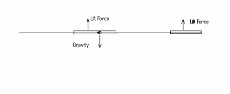
If we move the CG back pass the lift force then the following free body diagram presents the forces.

Note now the elevator lift force must be upward adding to the lift force of the wing to balance out the moments. This is good if we want to minimize the sink rate. This is also why when moving the CG farther back the sink rate gets lower. But there is a downside to this configuration and that is stability. As you move the CG back the stability of the model gets poorer.
In this example one knows pretty well where the CG of the glider is but how does one know where the lift force is on the wing or elevator? This brings up an entirely new subject on aerodynamic centers, which is not being discussed in this paper, but we will assume it to be ¼ of the chord of the lifting surface.
Stability
For a glider to have the best sink rate we want to create as much lift force as possible but at the same time create the least amount of drag. To further complicate things for a free flight glider, it needs to be stable and have a turn. I believe the best glider would be just a flat wing, creating as much lift as possible and the least amount of drag and would be the lightest because of only one part. But we need to have the glider stable, which means the forces about the CG must total up in equilibrium conditions to the ones shown in figure 1. Not only this but the glider must be able to automatically apply forces without any controls to get to these conditions given any reasonable upsets or start conditions. This is why the typically glider has an elevator, a rudder and the wing has dihedral. All of these things reduce the sink rate, but are need so the glider is stable and doesn’t come crashing to the ground.

